
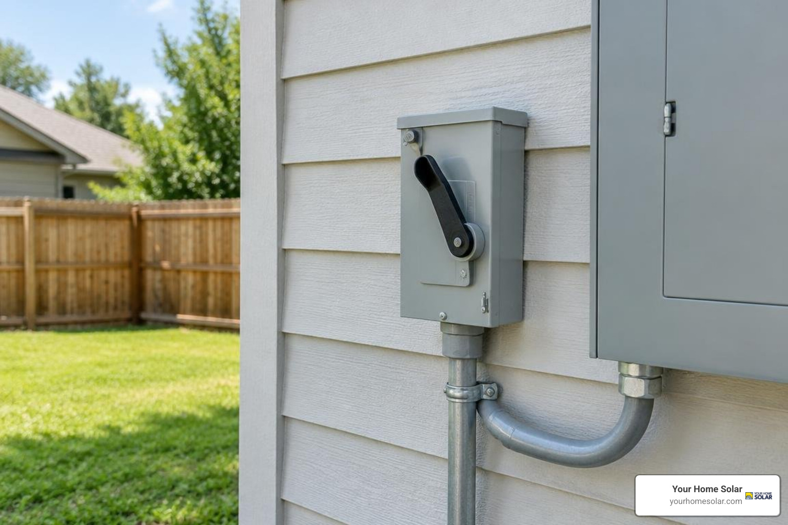
Generator Changeover Switch Installation Starts With Safe Isolation
Have a qualified electrician install the switch. They should size it for the generator and the circuits you need, fit a weather-rated generator inlet, and connect the utility and generator through a transfer device that cannot feed both sources at once. Before you use it, they must check the grounding and neutral setup, then test that the switch powers your home without backfeeding the grid. Do not connect a generator to a household outlet.
I’m Ernie Bussell, founder of Your Home Solar. My Navy quality-assurance work and years leading home solar operations taught me to treat generator changeover switch installation as a safety decision first, not just a way to keep the lights on.
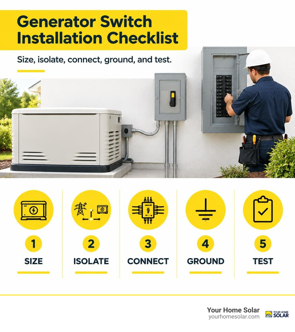
Generator changeover switch installation terms to know:
Understanding Generator Changeover Switches and Electrical Safety
A generator changeover switch (also known as a transfer switch) is a dedicated electromechanical mechanism designed to route electrical loads between two separate power sources: your primary utility grid and an auxiliary standby or portable generator.
The core safety principle governing any transfer hardware is break-before-make operation. This internal mechanical interlock physically breaks the connection to the incoming utility supply before it makes contact with the generator terminals. By maintaining physical isolation between power sources, the switch eliminates the possibility of the two out-of-phase AC supplies meeting, which would result in violent short circuits, fire hazards, and severe equipment destruction. Adhering to established electrical generator safety principles ensures your family and home remain fully protected whenever outages hit East Tennessee.
Manual Changeover Switch vs. Automatic Transfer Switch (ATS)
When evaluating backup equipment for your home, you will generally choose between manual mechanisms and automatic systems.
- Manual Changeover Switches (MTS): These devices use a heavy-duty rotary or toggle switch that features a distinct “centre-off” position (Position 1: Utility, Position 0: Off, Position 2: Generator). When grid power fails, you start your portable generator outdoors, plug in your heavy-duty cord to the exterior inlet, and physically turn the switch. They are cost-effective, robust, and commonly paired with portable units.
- Automatic Transfer Switches (ATS): An ATS uses internal logic controllers and electrically operated contactors to continuously monitor utility line voltage. When grid voltage dips or cuts out completely, the ATS commands a permanently installed standby generator to crank, senses stable output voltage and frequency, and transfers your load automatically—often achieving total switchover in under 10 seconds to satisfy critical safety standards.
To explore all options suited to your property, see the ultimate guide to home backup generator options.
| Feature | Manual Changeover Switch (MTS) | Automatic Transfer Switch (ATS) |
|---|---|---|
| Operation Mechanism | Physical lever / rotary knob | Microprocessor-controlled contactors |
| Response Time | 1 to 5 minutes (user-dependent) | Under 10 seconds |
| Typical Generator Pairing | Portable gas/diesel generators (3kW–10kW) | Fixed standby generators (10kW–26kW+) |
| System Cost | Lower upfront investment | Higher initial equipment investment |
| Operator Requirement | Requires manual startup and transfer | Operates completely unattended |
| Installation Location | Directly adjacent to main panel / subpanel | Indoor/Outdoor, often Service-Entrance Rated |
Preventing Grid Backfeeding and Complying with NEC Codes
The primary hazard of improper generator connection is backfeeding. If a generator is wired directly into a breaker panel without a mechanical interlock or transfer device, generator current can flow backward through the home’s service drop and into the neighborhood utility transformer. This steps up the 120/240-volt output back to thousands of volts on the local distribution lines, creating a lethal electrocution risk for utility line technicians working to restore grid power.
To eliminate this danger, the National Electrical Code (NEC) establishes strict guidelines:
- NEC Article 700 / 701: Dictates installation rules for emergency and legally required standby systems, mandating rapid load transfer and approved safety mechanisms.
- NEC Article 702: Applies directly to residential optional standby systems, requiring listed transfer equipment (tested to standards like UL 1008) to prevent the inadvertent interconnection of normal and alternate electrical sources.
Essential Planning and Sizing for Generator Changeover Switch Installation
Correctly engineering your backup setup requires matching the physical capacity of the switchboard, wiring, and inlet box to both your generator output and your real-world household power demands.
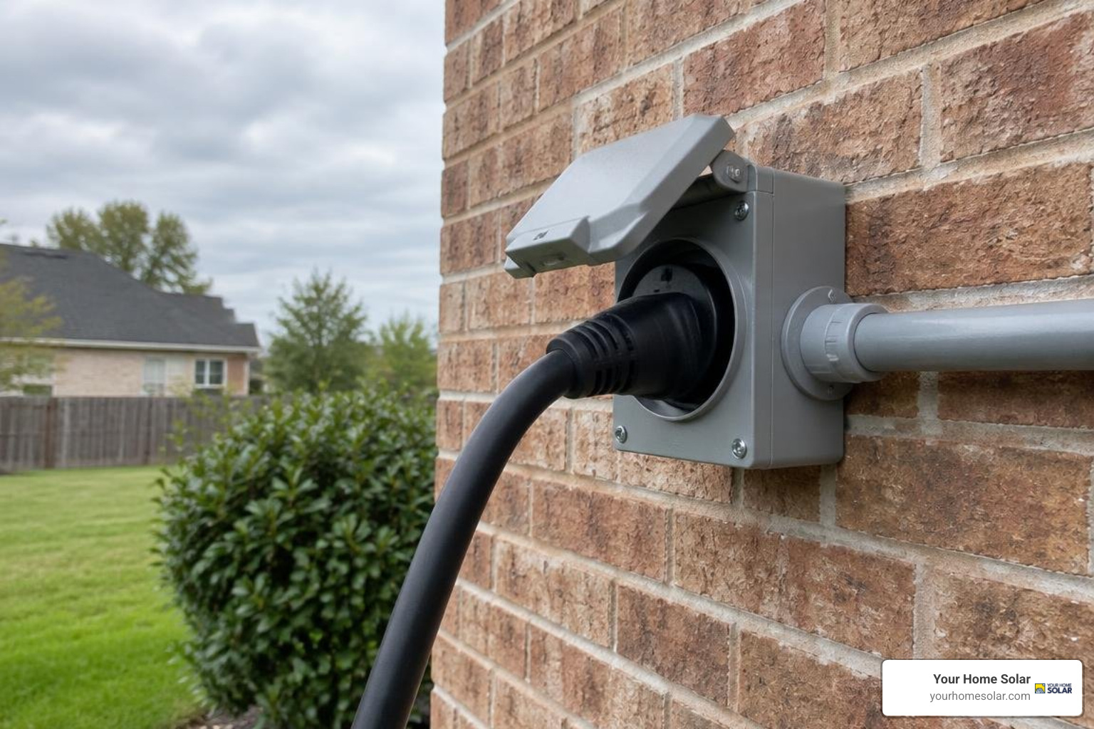
When sizing systems, it is vital to remember that a standard 6 kVA (roughly 5.2 kW) portable generator can run essential circuits such as lighting, refrigeration, well pumps, and internet routers. However, homeowners weighing gas setups against solar-plus-storage often look into comparing solar with traditional gas generators for East Tennessee homes to determine which system best manages ongoing fuel costs and storm protection.
Load Calculation and Cable Sizing Standards
Motor-driven appliances (refrigerators, HVAC blowers, sump pumps) draw starting (surge) wattage that can be three to four times their continuous running rating. Sizing conductors and circuit breakers solely on running load leads to nuisance tripping during motor inrush.
- 30-Amp Inlets & Switches: Suitable for generators up to 7,500 continuous running watts (at 240V, continuous current equals 31.25A, comfortably matched to a 30A/32A transfer circuit). Minimum conductor size: 10 AWG copper for very short runs, though 8 AWG or 6 AWG copper is preferred for longer runs to minimize voltage drop below 3%.
- 50-Amp Inlets & Switches: Suitable for generators producing 8,000 to 12,000 watts. Standard sizing requires minimum 6 AWG copper conductors.
- 100A to 200A Whole-House Switches: If routing utility lines directly through a whole-home transfer switch, line feeds must match the main service (such as 25 mm² or 2/0 to 4/0 AWG copper/aluminum depending on service rating).
For extensive multi-circuit or whole-home load configurations, review our step-by-step 200-amp transfer switch installation guide.
Grounding, Earth Rods, and Floating Neutral Considerations
Proper earthing protects human life from chassis faults and ensures safety protective devices operate reliably. Two main neutral-to-ground configurations dictate your earthing strategy:
- Floating Neutral Generators: The generator’s neutral conductor is isolated from the generator frame. When connected to a standard home panel, the generator frame bonds to the home’s primary grounding electrode system via the safety ground wire in the inlet cord. In this configuration, the transfer switch utilizes a solid neutral (the neutral is continuous and not switched), maintaining the single bond at the home’s main service panel.
- Bonded Neutral Generators: The generator has its neutral internally bonded to its metal chassis. If connected to a panel with a non-switched neutral, you create two separate ground-neutral bonds, resulting in circulating neutral currents across ground conductors and nuisance tripping of Ground Fault (GFCI/RCD) devices. In these cases, you must either remove the bond at the generator (turning it into a floating unit) or install a switched neutral (3-pole for single-phase, 4-pole for 3-phase) to treat the generator as a Separately Derived System.
For standalone auxiliary earthing or off-grid farm setups, installing two coupled 1.2-meter, 16mm earth rods driven into the ground can achieve an earth electrode resistance target well below 200 ohms (ideally in the 50 to 70 ohm range).
Step-by-Step Single-Phase Generator Changeover Switch Installation
Executing a safe installation requires strict adherence to lockout/tagout procedures, systematic wiring steps, and accurate terminal torquing.
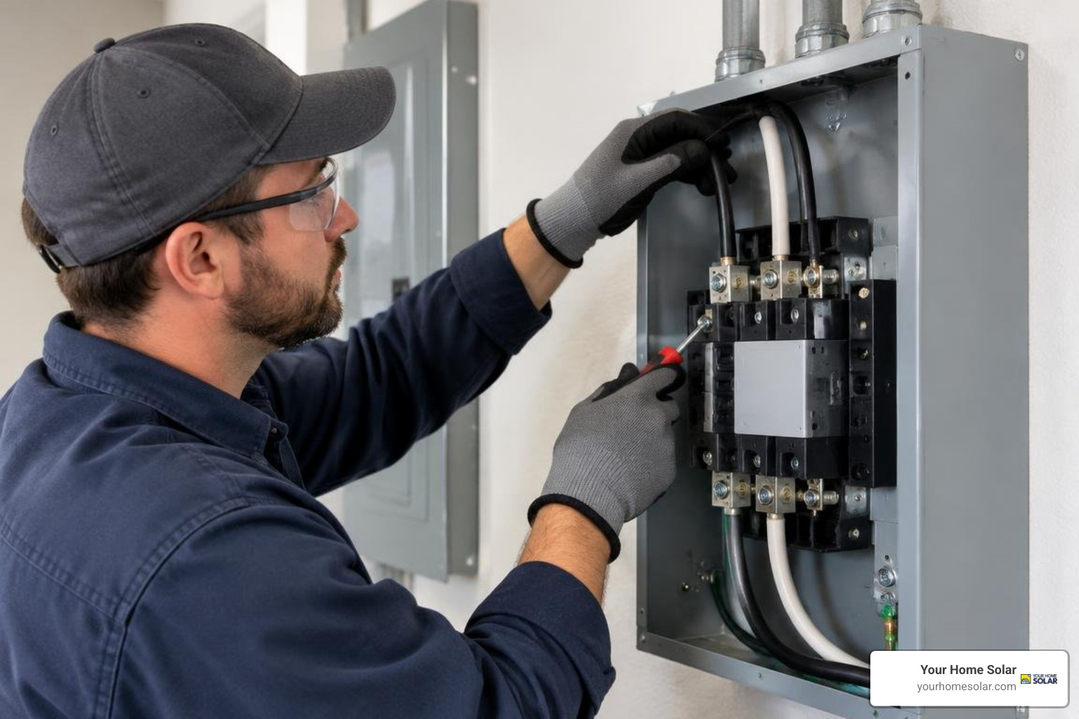
Before beginning physical wiring, always review our guide on hooking up a generator to your fuse box to understand panel layouts and breaker placement.
Required Tools and Site Preparation
Assemble your tools and personal protective equipment (PPE) before starting:
- Insulated screwdriver set (1,000V rated, Pozidriv and Slotted)
- Digital Multimeter with True-RMS AC/DC voltage and continuity testing
- Calibrated torque wrench or torque screwdriver
- Wire strippers, conduit bender, and linesman pliers
- High-impact protective eyewear and insulated electrical gloves
- Appropriately rated C-curve Miniature Circuit Breaker (MCB) for generator circuit feed
Step-by-Step Wiring Sequence for Single-Phase Systems
- De-Energize Utility Service: Switch off the main service disconnect breaker feeding the distribution board. Test the input lugs with a verified digital multimeter to confirm zero residual voltage.
- Mount the Changeover Enclosure: Fix the changeover enclosure adjacent to the main panelboard using masonry screws or heavy-duty anchors at eye level. Install protective PVC or metallic conduit between the two enclosures.
- Connect Utility Terminals: Route the utility supply feed conductors (Line 1, Line 2 for split-phase 120/240V or Line and Neutral for 230V systems) to the designated “Utility/Normal” terminals on the switch.
- Connect Generator Input: Run matching gauge conductors from the external weather-resistant generator power inlet box through dedicated conduit into the “Generator/Standby” terminals of the switch.
- Route Switch Load Terminals: Wire the output (“Load”) terminals of the changeover switch directly into the main panel busbars or the dedicated critical-loads subpanel.
- Terminate Neutral and Ground Conductors: Connect all equipment grounding conductors directly to the main grounding bus. If the system utilizes a solid non-switched neutral, land the generator neutral directly on the distribution neutral bar in accordance with NEC and IEC generator connection standards.
Handling Three-Phase 4-Pole Switch Connections
Commercial operations, agricultural sites, and larger properties running three-phase supplies (120/208V or 230/400V) require a 4-pole changeover switch that safely isolates all three active phases (L1, L2, L3) plus the neutral conductor.
When installing a 4-pole switch, ensure the device features early-make, late-break neutral contacts. The neutral pole must mechanically close before the three line contacts engage during transfer, and break after the phase contacts disconnect. This prevents floating neutral conditions during switching, protecting delicate 120V or single-phase electronics connected between line and neutral from overvoltage destruction. For detailed terminal schematics, consult the official Hager changeover switch wiring diagrams.
Testing, Commissioning, and Avoiding Common Installation Mistakes
Careful testing confirms that all internal contacts seat correctly and voltages remain balanced under active electrical load.
Common Mistakes to Avoid
- Undersized Neutral Conductors: Unbalanced 120V single-phase loads on a 240V generator return significant current through the neutral wire. Never reduce neutral conductor gauge below the phase conductor sizing.
- Loose Terminal Terminations: Loose screw terminals create high contact resistance, causing overheating and terminal melting under load. Always torque terminals to manufacturer-specified inch-pounds using a torque screwdriver.
- RCD / GFCI Tripping on Generator Startup: Occurs when a bonded-neutral portable generator is connected through a transfer switch that does not switch the neutral, creating dual neutral-to-ground return paths.
Best Practices to Complete Your Generator Changeover Switch Installation
- Install an Upstream Isolator Switch: Placing a dedicated lockable isolator switch adjacent to the changeover unit gives service technicians an added layer of safety isolation during routine maintenance.
- Incorporate Status Indicator Lamps: Mount LED indicator lamps on the panel face—one showing utility availability and one showing generator availability. This lets you see when grid power has returned without cycling the switch back and forth.
- Ensure Weatherproof Inlet Protection: Use outdoor inlets rated minimum NEMA 3R or IP66 with spring-loaded weatherproof covers positioned away from roof runoff.
- Clearly Label All Circuits and Switches: Affix engraved placards and laminated operation instructions adjacent to the panel so anyone in the home can execute safe power transfers during an emergency.
Post-Installation Commissioning and Voltage Testing
Follow this commissioning sequence prior to handing over the system:
- Static Continuity & Insulation Resistance Testing: With power off, verify complete physical isolation between Utility and Generator terminals across all switch positions.
- Utility Voltage Verification: Re-energize the utility supply. Set the changeover switch to Position 1. Measure phase-to-neutral (120V/230V) and phase-to-phase (240V/400V) at the load distribution panel.
- Generator Transfer Simulation: Turn off the main utility breaker. Move the changeover switch to Position 0 (Off). Start the generator outside, connect the cord to the inlet, verify generator output voltage, and flip the changeover switch to Position 2 (Generator).
- Load Step Testing: Engage home circuit breakers one by one, monitoring voltage and engine speed to verify that generator frequency remains stable without excessive voltage drop.
Frequently Asked Questions About Generator Switch Panels
Can a portable generator power my entire home through a changeover switch?
A portable generator can power an entire home only if its total running wattage matches your electrical demand. Most residential portable units (5 kW to 10 kW) are intended to power essential circuits (refrigeration, lighting, water heating, communications). Running high-demand central air conditioning or electric heating typically requires a larger standby unit or systematic load management.
Do I need to switch the neutral wire when installing a changeover switch?
You must switch the neutral wire (using a 3-pole switch for single-phase or a 4-pole switch for three-phase) if your generator has an internal, non-removable neutral-to-ground bond, making it a Separately Derived System. If the generator has a floating neutral, the neutral is not switched; it lands solidly on the main panel neutral bar, preserving the home’s single grounding bond.
What size changeover switch do I need for a 7,500-watt generator?
A 7,500-watt generator produces 31.25 amps at 240 volts. A 30-amp or 32-amp transfer switch paired with a 30-amp inlet and 10 AWG (or 8 AWG) copper wire is the standard minimum match, while upgrading to a 50-amp switch allows future expansion if you upgrade to a larger generator later.
Conclusion
A properly executed switch installation provides reliable storm resilience while protecting your home and utility workers from hazardous electrical backfeeding. Whether you are running a portable 6 kVA generator or a whole-house standby unit, precision wiring, code-compliant earthing, and listed transfer hardware are essential.
At Your Home Solar, we take pride in delivering clean, compliant, and durable energy backup systems tailored to your property. If you want peace of mind knowing your backup power is installed safely, contact our team for expert generator installation in Knoxville and throughout East Tennessee.