
Safely Hook Up a Generator to a Breaker Box
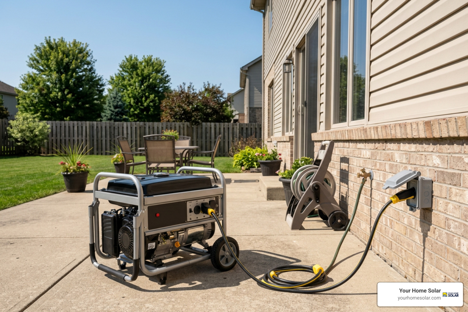
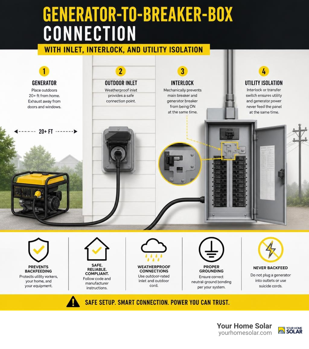
To safely hook up a generator to breaker box, use a weatherproof outdoor power inlet connected through a manual transfer switch or a panel-specific mechanical interlock kit. These devices make it mechanically impossible for utility power and generator power to feed the panel at the same time.
Never plug a generator into a wall outlet, dryer outlet, or a double-male “suicide cord.” That unsafe practice, called backfeeding, can energize utility lines and seriously injure lineworkers. It can also damage your generator, panel, and appliances.
Before any outage, make sure your system has:
- A listed transfer switch or interlock made for your exact panel
- A properly sized outdoor inlet box and four-wire generator cord
- Correct wire and breaker sizing for the generator output
- A generator placed outdoors at least 20 feet from the home, with exhaust facing away from doors, windows, and vents
- Proper neutral-ground bonding for the transfer equipment you use
The Consumer Product Safety Commission documented at least 742 portable-generator carbon monoxide deaths in the United States from 2012 through 2022. Safe placement and proper electrical isolation are not optional details. They are the foundation of backup power that protects your household and the people working on the grid.
I am Ernie Bussell, founder of Your Home Solar, with a background in Navy quality assurance, operations, and homeowner energy education. That experience shapes the safety-first approach in this guide to help East Tennessee homeowners hook up generator to breaker box systems without dangerous shortcuts.
Discover more about hook up generator to breaker box:
Safe Connection Methods to Hook Up Generator to Breaker Box
When bringing backup power into your home, you cannot rely on good intentions or memory to prevent electrical accidents during a chaotic blackout. The National Electrical Code (NEC Article 702.5) strictly mandates that any transfer equipment used to connect an optional standby power system must mechanically isolate the standby power source from the utility grid.
This requirement enforces a “break-before-make” design. The connection to your utility grid must physically break open before the connection to your generator can close. This mechanical rule ensures that electricity can only flow from one source at a time into your breaker box.
There are two primary NEC-compliant methods for safely connecting a portable generator to your service panel: a dedicated manual transfer switch and a listed mechanical interlock plate.
| Feature / Metric | Manual Transfer Switch | Mechanical Interlock Kit |
|---|---|---|
| National Electrical Code Compliance | NEC Article 702.5 Listed | NEC Article 702.5 Listed |
| Circuit Selection | Dedicated subpanel (6–10 pre-wired circuits) | Entire main panel (manual circuit breaker management) |
| Estimated Equipment Cost | $300 – $600 | $50 – $150 |
| Typical Professional Installation Cost | $900 – $1,900 (Labor + Materials) | $450 – $900 (Labor + Materials) |
| Flexibility During an Outage | Fixed to hardwired circuits only | Flexible (power any circuit within generator wattage) |
| Neutral Switching Capability | Available (3-pole switches can switch neutral) | Does not switch neutral (shares main panel neutral bar) |
| Installation Complexity | Higher (requires re-routing individual branch circuits) | Lower (requires breaker space & dedicated backfeed breaker) |
When planning your setup, a dedicated 200 amp transfer switch installation guide details the full conduit, wiring, and subpanel layout for high-capacity transfer equipment.
Manual Transfer Switch vs. Panel Interlock Kit
A manual transfer switch functions as a pre-selected subpanel installed directly beside your main electrical box. During installation, an electrician reroutes critical circuits—such as your refrigerator, well pump, furnace blower, and select lighting groups—into the transfer subpanel. Each circuit on the switch features a three-position toggle: Utility (LINE), OFF, and Generator (GEN). This setup prevents human error, as you cannot accidentally overload the generator with unselected household loads. However, it locks you into those specific pre-wired circuits unless you open the panel to re-wire them.
A mechanical interlock kit uses a precision-machined steel or aluminum sliding plate installed directly over your main panel cover. The plate works by creating a mechanical barrier: you cannot flip the dedicated generator backfeed breaker on until the main utility breaker is physically switched off.
This grants you whole-panel flexibility, allowing you to energize any circuit in your home—provided your generator has sufficient wattage. It requires strict operational discipline to turn off heavy draw appliances before switching the generator on.
When evaluating equipment investments, our generator installation cost guide offers a deeper look at budgeting for panels, permits, and professional labor across Tennessee.
Why Backfeeding and Suicide Cords Are Dangerous and Illegal
Attempting to power a home by connecting a generator directly into a standard 120V wall outlet or a 240V dryer outlet using a male-to-male plug (often called a “suicide cord”) is dangerous and illegal under NEC 702.5.
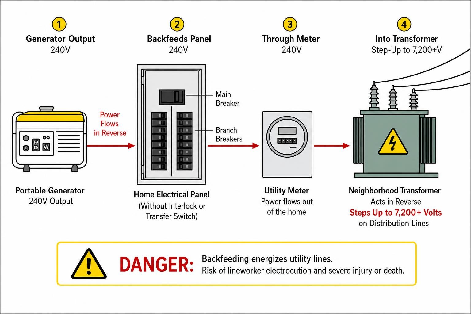
When you backfeed an electrical panel without a mechanical interlock or transfer switch isolating the main service lines, power flows in reverse out of your panel, through the utility meter, and into the local distribution transformer. That neighborhood step-down transformer—which normally converts 7,200 volts from utility poles down to 120/240 volts for household use—works in reverse as a step-up transformer. It converts the 240V generator output back into 7,200+ volts on the exterior distribution lines.
The real-world consequences of this practice are severe:
- Lineworker Electrocution: In June 2020, OSHA documented an incident where a utility lineworker was hospitalized after receiving a severe electrical shock from a line energized by a homeowner’s generator backfeed. A separate NIOSH investigation confirmed a line technician’s death under identical circumstances during post-storm restoration work.
- Exposed Live Terminals: A double-male cord plugged into a running generator leaves two exposed brass prongs carrying 120V or 240V of live electricity before you make the second connection. Touching these prongs causes severe electrical burns or cardiac arrest.
- Generator and Panel Destruction: If utility power is suddenly restored while your generator is backfeeding the panel out of phase, the massive inrush current will instantly vaporize generator windings, blow breakers off the busbar, and trigger an electrical fire.
- Insurance Forfeiture: Electrical fires or property damage resulting from unpermitted, unlisted, and non-code-compliant backfeeding connections can void standard homeowner property insurance policies.
To explore the safety principles of whole-home connections in more detail, review how to connect a generator to a breaker box safely.
System Compatibility: Bonding, Codes, and Safety Clearances
Before touching a single wire or purchasing conduit, you must review the installation environment, electrical code requirements, and local municipal permits across East Tennessee. Every county—from Knox, Blount, and Sevier to Washington and Sullivan—requires building permits and electrical inspections for main service panel alterations.
Proper planning keeps your family safe and helps you implement smart strategies for staying powered during grid outages.
The 20-Foot Rule and Carbon Monoxide Prevention
Carbon monoxide (CO) is a colorless, odorless, and tasteless combustion byproduct that claims lives during storm recovery. The CPSC recorded 742 deaths from portable generator carbon monoxide poisoning between 2012 and 2022, with an annual average of roughly 85 deaths between 2017 and 2019.
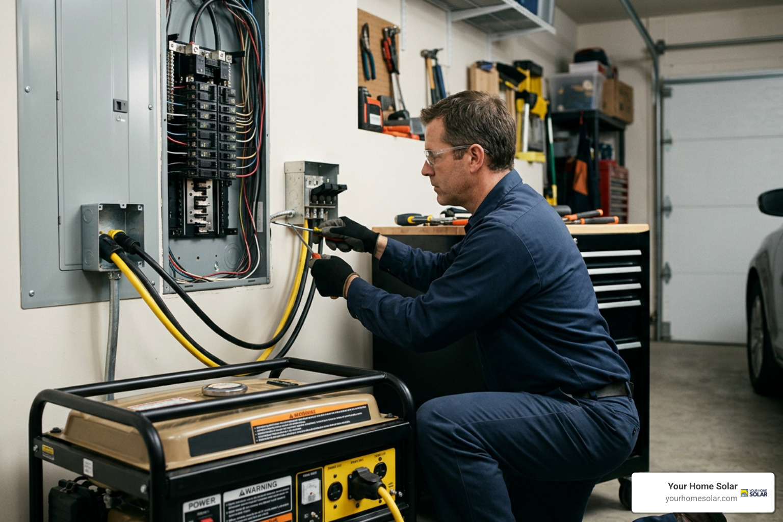
The CPSC mandates a strict operational boundary: Operate generators outdoors only, at least 20 feet away from homes and occupied structures, with the exhaust directed entirely away from windows, doors, soffit vents, and HVAC fresh-air intakes.
Never operate a generator in:
- Garages (even with the main vehicle door completely open)
- Carports, screened-in porches, or covered breezeways
- Basements, crawlspaces, or utility sheds adjacent to living areas
Modern portable generators meeting ANSI/PGMA G300-2023 or UL 2201 standards feature automated CO shutoff sensors. ANSI/PGMA G300 requires engine shutdown if CO concentrations reach 600 ppm instantaneously or a 400 ppm 10-minute running average. UL 2201 requires shutdown at 400 ppm instantaneous and 150 ppm average.
These automated sensors serve as emergency secondary safety devices—never treat them as permission to place a generator closer than 20 feet from your home.
Neutral-Ground Bonding Rules: Floating vs. Bonded Neutral
One of the most common code violations in DIY generator installations involves the configuration of the neutral-to-ground bond. The National Electrical Code permits only one neutral-to-ground bond across an entire residential electrical system to prevent stray circulating current on equipment grounding conductors.
- Floating Neutral (Required for standard interlocks and solid-neutral transfer switches): The main electrical service panel already contains a bonding jumper connecting the neutral bar to the metal enclosure and grounding electrode system. Because a standard mechanical interlock or 2-pole transfer switch does not switch the white neutral wire, the generator’s neutral conductor remains connected to the main panel’s neutral busbar. Therefore, the generator must have a floating neutral (neutral isolated from the generator frame). If you connect a bonded-neutral generator, you create a dual bond. This causes return current to flow over the safety grounding wire, creating shock hazards and tripping generator-mounted GFCI breakers.
- Bonded Neutral (Required for 3-pole switched-neutral transfer switches): If your transfer switch switches both the hot conductors and the neutral conductor simultaneously, the generator is classified by the NEC as a Separately Derived System. In this specific setup, the generator must have its internal neutral-to-ground jumper installed to provide an effective ground-fault current path.
Review the manufacturer’s internal wiring schematic before initial operation. Most portable generators ship from the factory with the neutral bonded to the frame for jobsite use. Unbonding the neutral typically involves opening the alternator end-bell cover and disconnecting the white neutral jumper wire from the green ground terminal screw.
For additional context on cable configurations and safe isolation hardware, check out cords, cables, and transfer switch setup.
Equipment Sizing and Required Components
Connecting a generator to your panel requires a complete, code-compliant power delivery path:
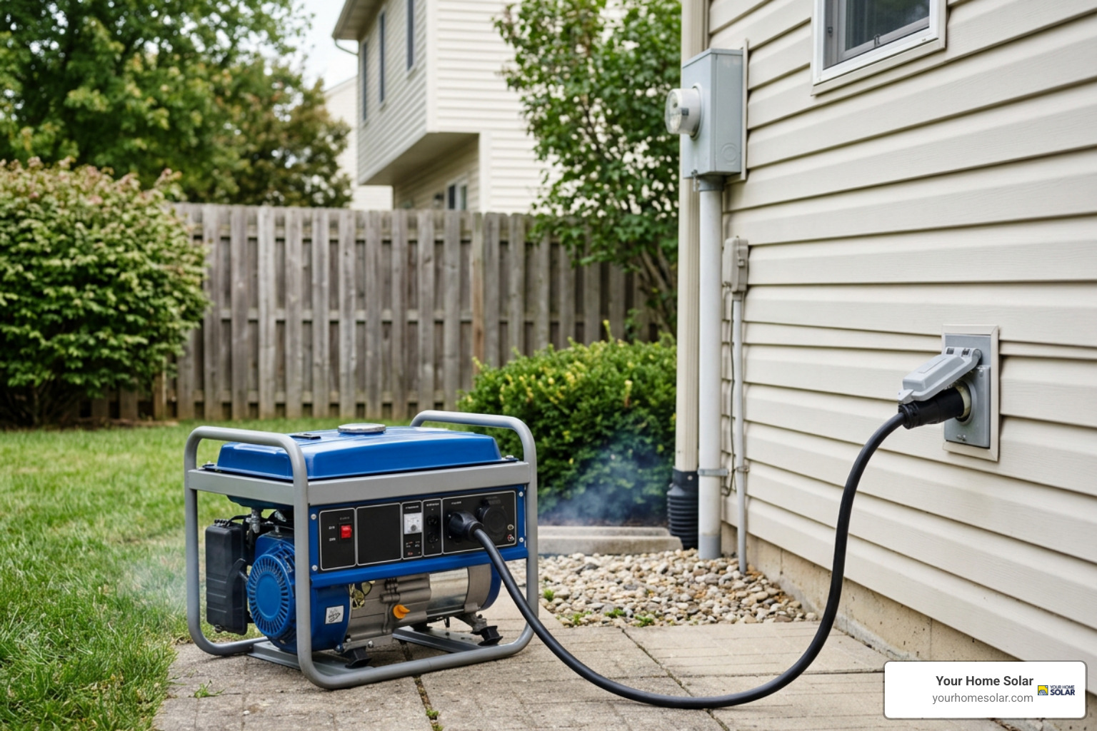
- Weatherproof Power Inlet Box (NEMA 3R): A surface-mounted exterior box with recessed male prongs that accepts the generator cord. Common configurations include a NEMA L14-30P (30-amp, 125/250V twist-lock) or a CS6375 / NEMA 14-50P (50-amp, 125/250V straight/twist-blade).
- Heavy-Duty 4-Wire Generator Power Cord: An outdoor-rated flexible cable (SOOW, SJTW, or STW) with four conductors: Hot 1 (Black), Hot 2 (Red), Neutral (White), and Ground (Green).
- Dedicated Double-Pole Generator Breaker: A 2-pole breaker installed in the top-right or top-left position of your main breaker box directly adjacent to the main breaker, allowing the interlock slider plate to mechanically toggle between them.
- Liquid-Tight Conduit and Electrical Fittings: PVC, metallic EMT, or flexible liquid-tight conduit connecting the exterior inlet box to the panel enclosure.
Required Wire Gauges to Hook Up Generator to Breaker Box
Conductor sizing must match the ampacity of your generator inlet box and dedicated backfeed breaker to eliminate fire risks caused by resistance heating:
- 30-Amp System (Up to 7,500 running watts): Requires a minimum of 10 AWG copper wire (e.g., 10/3 with ground NM-B Romex indoors or THHN/THWN-2 conductors inside conduit). Protect this run with a 30-amp double-pole breaker.
- 50-Amp System (Up to 12,000 running watts): Requires a minimum of 6 AWG copper wire (e.g., 6/3 with ground NM-B or individual 6 AWG THHN conductors in conduit). Protect this run with a 50-amp double-pole breaker.
Under NEC 705.12 (The 120% Busbar Rule), electrical inspectors require that the sum of the main service disconnect rating and the generator backfeed breaker rating cannot exceed 120% of the panel busbar’s total rated ampacity. For a standard 200-amp main panel with a 200-amp rated busbar:
$$\text{Maximum Total Protection} = 200\text{ A} \times 120\% = 240\text{ A}$$
Subtracting the 200-amp main breaker leaves a maximum allowable generator backfeed breaker size of 40 amps unless the panel carries a higher busbar rating (such as a 200-amp main breaker on a 225-amp rated busbar). An electrician must verify your panel label ratings before adding a backfeed breaker.
Critical Load Calculation and Power Quality
Sizing your electrical loads correctly ensures you don’t stall your generator when inductive loads switch on. You must calculate both running (continuous) watts and starting (surge) watts for your critical appliances.
$$\text{Generator Sizing Budget} = \text{Sum of Continuous Watts} + \text{Highest Single Motor Starting Surge} + 20\%\text{ Safety Headroom}$$
Common starting and running wattages for critical home loads:
- Refrigerator / Freezer: 700–800 running watts / 1,500–2,200 starting watts
- Well Pump (1/2 HP): 1,000 running watts / 2,100 starting watts
- Furnace Blower Motor: 600–900 running watts / 1,500–2,000 starting watts
- Sump Pump (1/3 HP): 800 running watts / 1,300 starting watts
- LED Lighting & Router: 150–300 running watts / 0 starting watts
Total Harmonic Distortion (THD) is another key factor for modern homes. Standard open-frame portable generators can produce a THD of 12% to 25%, causing voltage fluctuations that can overheat microprocessor boards in smart refrigerators, high-efficiency variable-speed HVAC systems, and computers. For sensitive electronics, choose an inverter generator or clean-power standby system delivering pure sine wave output with less than 3% to 5% THD.
If you are evaluating whether fossil-fuel generators or battery solutions fit your home layout better, read our guide on comparing solar and gas backup options.
Step-by-Step Procedure to Safely Connect and Operate Your Generator
Operating a generator connected to your main breaker box requires following a precise sequence. Print this procedure and keep it attached to the inside door of your electrical service panel.
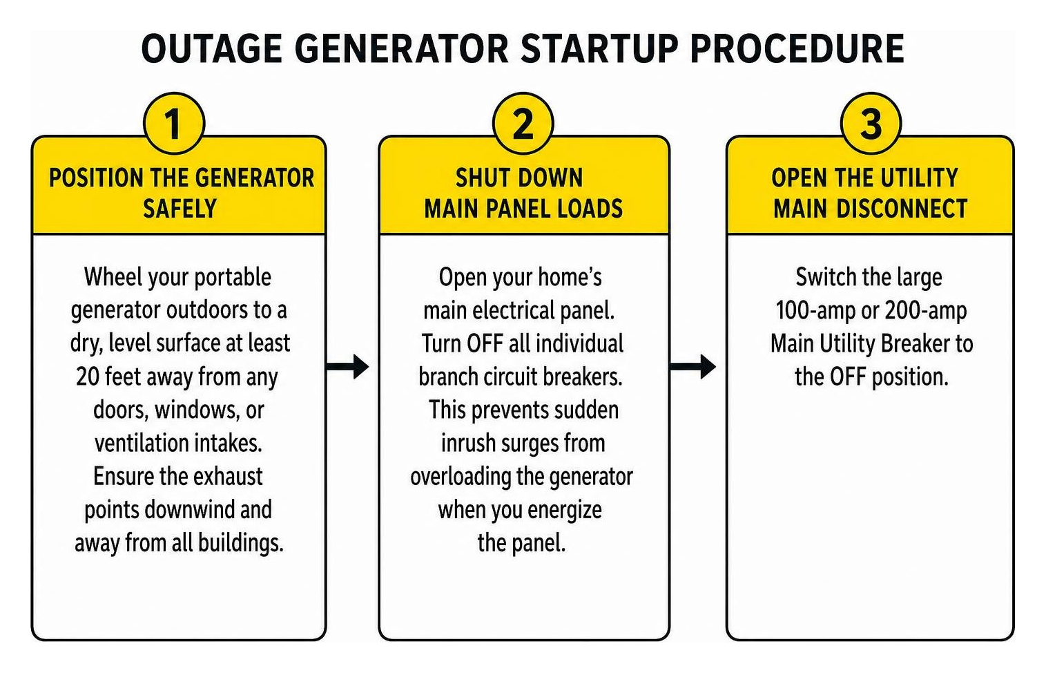
The Outage Startup Sequence to Hook Up Generator to Breaker Box
- Position the Generator Safely: Wheel your portable generator outdoors to a dry, level surface at least 20 feet away from any doors, windows, or ventilation intakes. Ensure the exhaust points downwind and away from all buildings.
- Shut Down Main Panel Loads: Open your home’s main electrical panel. Turn OFF all individual branch circuit breakers. This prevents sudden inrush surges from overloading the generator when you energize the panel.
- Open the Utility Main Disconnect: Switch the large 100-amp or 200-amp Main Utility Breaker to the OFF position.
- Engage the Mechanical Interlock Plate: Slide the mechanical interlock plate upward (or downward, depending on your panel model) into the channel vacated by the open main breaker handle. This unblocks the handle of your generator backfeed breaker.
- Connect the 4-Wire Power Cord: Plug the female end of your heavy-duty 4-wire cord into the outdoor power inlet box and twist it clockwise to lock. Connect the male end to the matching 120/240V receptacle on your generator.
- Start the Generator Unloaded: Ensure the generator’s onboard circuit breaker is switched OFF. Start the engine following manufacturer instructions (fuel valve open, choke set, pull cord or electric start). Let the engine idle and warm up for 2 to 3 minutes until voltage and frequency stabilize.
- Close the Generator Output Breaker: Flip the generator’s onboard master circuit breaker to the ON position.
- Energize the Panel Backfeed Breaker: Walk inside to your electrical panel. Switch the dedicated generator double-pole breaker to the ON position. Your panel busbars are now energized by the generator.
- Sequentially Activate Critical Branch Circuits: Turn on your critical branch breakers one by one, starting with the largest inductive motor load first (such as a well pump or refrigerator). Allow the motor to stabilize before turning on the next breaker. Keep your total continuous load within 80% of your generator’s rated continuous output.
Utility Power Restoration and Safe Shutdown Sequence
When power returns to your neighborhood, manage the transition without backfeeding or damaging the generator:
- Confirm Utility Restoration: Check whether your neighborhood streetlights or utility-sensing indicator lamps on your panel have illuminated.
- Shed Household Loads: Switch OFF all individual branch circuit breakers in your panel one at a time.
- Open the Generator Backfeed Breaker: Flip the dedicated generator double-pole breaker to the OFF position.
- Slide the Mechanical Interlock Plate: Move the interlock plate back into its resting position, blocking the generator breaker handle and freeing the main service disconnect handle.
- Close the Main Utility Breaker: Switch the large Main Utility Breaker back to the ON position.
- Restore Branch Circuits: Turn your individual branch circuit breakers back ON sequentially.
- Generator Cooldown and Engine Shutdown: Walk outside to the generator. Turn OFF the generator’s onboard breaker. Let the engine run unloaded for 3 to 5 minutes to dissipate internal rotor heat. Turn the engine ignition switch to OFF and shut off the fuel supply valve.
- Disconnect and Cool Down for Refueling: Unplug the power cord from the inlet box and the generator. If you need to refuel the generator for subsequent use, let the engine cool for at least 15 to 20 minutes before pouring gasoline. Fuel spilled onto a hot exhaust manifold can ignite instantly.
Frequently Asked Questions About Connecting a Generator to a Breaker Box
Is it illegal to hook up a generator without a transfer switch or interlock?
Yes. Connecting a portable or standby generator directly to a home service panel without an NEC-approved mechanical isolation device (such as a UL-listed manual transfer switch or an engineered mechanical interlock plate) violates NEC Article 702.5 and local municipal electrical codes.
Utility companies also prohibit unisolated backfeeding under their connection agreements because it puts lineworkers at risk of electrocution. Doing so can lead to immediate service disconnection, civil liability, and voided property insurance policies.
Can I connect a 50-amp generator to a 30-amp inlet box?
You should not connect a 50-amp generator output to a 30-amp inlet box using step-down adapter cords. A 30-amp inlet box, its internal wiring, and the 10 AWG copper conductors are rated to safely carry a maximum continuous load of 24 amps (80% of rated capacity).
If a 50-amp generator supplies power through a 30-amp inlet without a dedicated 30-amp breaker at the source, the 10 AWG conductors inside your wall can overheat before the generator’s onboard 50-amp breaker trips, creating an electrical fire hazard. Always match your inlet box, wire gauge, and panel breaker ampacity to your generator’s maximum rated output.
Do I need a professional electrician to install my generator connection?
Yes, hiring a licensed electrician is strongly recommended for any work inside your main service panel. Installing an inlet box, running conduit through exterior walls, adding a dedicated 240V backfeed breaker, and fitting a listed interlock plate involves working near unshielded main service lugs that remain live even when the main breaker is off.
A licensed electrician will ensure correct conductor sizing under NEC 705.12, verify single-point neutral bonding, balance multi-wire branch circuits, pull municipal permits, and schedule mandatory county electrical inspections.
Reliable Backup Power for Your Home
Hooking up a generator to your breaker box gives you reliable, whole-panel control during unexpected grid disruptions. By installing a listed mechanical interlock kit or transfer switch, adhering to the CPSC 20-foot outdoor clearance rule, and following a step-by-step connection sequence, you can keep your essential household systems running safely without risking electrical backfeed or carbon monoxide hazards.
If you are ready to upgrade your home with a code-compliant backup power system, our certified team at Your Home Solar is here to help. We provide tailored, turnkey energy installations across Knoxville and throughout East Tennessee. Contact our team today to schedule your professional generator installation in Knoxville and keep your lights on during the next big storm.