
Why Understanding a 3-Phase EV Charger Wiring Diagram Matters
A 3 phase ev charger wiring diagram is crucial for installing a high-power EV charging station, particularly in commercial or future-proofed residential settings. Key aspects include:
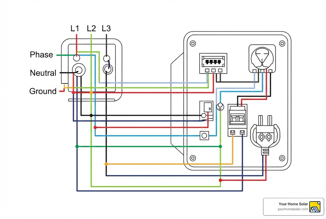
- Power Connections: Three live wires (L1, L2, L3), one neutral (N), and one protective earth (PE)
- Voltage: Typically 400V AC in a Wye configuration
- Amperage: Usually 32A per phase, delivering up to 22kW of charging power
- Circuit Protection: Requires a three-pole circuit breaker rated at 125% of continuous load (typically 40A for a 32A charger)
- Safety Devices: Type A or Type B RCD (Residual Current Device) with DC fault detection
- Control Wiring: Includes Control Pilot (CP) and Proximity Pilot (PP) pins per SAE J1772 standard
Three-phase charging is significantly faster than single-phase. A single-phase charger maxes out around 7.4kW, while a three-phase charger delivers up to 22kW. This means charging at 80+ miles of range per hour, compared to just 28.
For East Tennessee homeowners, faster charging means more flexibility. Understanding these wiring needs is key to making informed decisions about your electrical infrastructure, especially if an EV is part of your energy independence plan.
Most US homes use single-phase or split-phase power. Three-phase is common in commercial settings, but some newer homes or properties with solar may have it, making high-speed charging a realistic option.
The diagram shows current flow from the main panel to the vehicle. Getting this right is critical for safety, performance, and code compliance.
I’m Ernie Bussell, founder and CEO of Your Home Solar, and I’ve spent years helping homeowners steer complex energy systems, from solar installations to EV charging infrastructure. Understanding a 3 phase ev charger wiring diagram is part of building a complete home energy solution that works safely and efficiently for decades.
, typical voltage (240V vs 400V), maximum charging power (7.4kW vs 22kW), and charging speed comparison (28 miles per hour vs 80+ miles per hour). Visual includes simple wiring diagrams for both configurations with labeled L1, L2, L3, N, and PE connections. - 3 phase ev charger wiring diagram infographic")
Single-Phase vs. Three-Phase: What’s the Difference?
The difference between single-phase and three-phase power is how electricity is delivered. This impacts charging speed, efficiency, and the complexity of the 3 phase ev charger wiring diagram.
Single-phase power, common in East Tennessee homes, uses one AC waveform. It’s fine for most appliances and Level 1/2 EV chargers, offering up to 7.4 kW.
Three-phase power uses three offset AC waveforms for a constant power flow, ideal for high-power needs. For EV charging, this means faster speeds up to 22 kW. It’s typically found in commercial buildings or large residential properties.
The wiring also differs. Single-phase uses Line (L1), Neutral (N), and Protective Earth (PE). North American split-phase systems add a second line (L2) for 240V. Three-phase requires three lines (L1, L2, L3), a Neutral (N), and PE for a Wye connection, increasing the diagram’s complexity.
Voltage also varies. Single-phase is often 240V AC, while three-phase systems use higher voltages like 400V AC. This allows for greater power transfer and faster charging.
Key Distinctions in Wiring
Let’s dig a bit deeper into the wiring itself.
For single-phase wiring, you’ll connect L1, N, and PE. In North American split-phase systems, you’d have L1, L2, N, and PE for 240V. The charger draws power from these connections.
Three-phase wiring is more complex, connecting L1, L2, L3, N, and PE. The goal is to balance the electrical load across the phases for efficiency and grid health. Standard practice involves connecting all these conductors to the terminal block.
Here’s a quick comparison:
| Feature | Single-Phase EV Charger Wiring | Three-Phase EV Charger Wiring |
|---|---|---|
| Conductors | L1, N, PE (or L1, L2, N, PE for split-phase) | L1, L2, L3, N, PE |
| Voltage | 230V-240V AC (line-to-neutral/line-to-line) | 400V AC (line-to-line), 230V AC (line-to-neutral) |
| Power Output | Up to 7.4 kW (e.g., 32A @ 230V) | Up to 22 kW (e.g., 32A @ 400V) |
| Charging Speed | Moderate (approx. 28 miles/hour) | Fast (approx. 80+ miles/hour) |
| Best For | Residential, typical daily charging | Commercial, fleet, high-demand residential, future-proofing |
More info about EV Charger Installation Knoxville
Why Choose Three-Phase?
The main reason for three-phase is speed and efficiency. With up to 22 kW, you can drastically cut charging times. Products like the Tesla Wall Connector, SolarEdge Home EV Charger, and Chargemaster 22Kw H22S2 all support this power level.
For commercial properties in Knoxville, Maryville, or Johnson City, this means faster turnaround for fleet vehicles and customers. A 22kW charger maximizes operational efficiency for businesses with multiple EVs.
For residential use, especially in larger homes or those with multiple EVs, a three-phase setup is a smart future-proofing move. As battery capacities grow, so will the need for faster charging. If your East Tennessee property can accommodate it, a three-phase charger offers best convenience and aligns with our commitment to high-performance home energy solutions.
Decoding the 3-Phase EV Charger Wiring Diagram
A 3 phase ev charger wiring diagram can seem complex, but it’s a roadmap for how power and communication signals work together. Breaking it down reveals the crucial role of each component in delivering power safely to your EV.
, main contactor, control board, current transformers (CTs), RCD, and the charging cable with CP and PP lines. - 3 phase ev charger wiring diagram")
Understanding the Power Connections in a 3-Phase EV Charger Wiring Diagram
Power connections are the charger’s backbone. A three-phase system handles substantial power (typically 400V), requiring careful attention to the wiring diagram.
- Line Conductors (L1, L2, L3): These are the three “hot” wires that carry the alternating current from your electrical panel to the charger.
- Neutral (N): The neutral wire provides the return path for the current and is essential for completing the circuit.
- Protective Earth (PE): This is your safety ground wire, providing a safe path for fault currents to flow.
These conductors connect to the charger’s terminal blocks. For example, the Tesla Wall Connector specifies connecting L1, L2, L3, neutral, and ground to its terminal block.
Wire sizing is critical. A 22kW three-phase charger at 400V draws 32A per phase, so wiring must handle this continuous load. For example, the SolarEdge Home EV Charger specifies a minimum of 5 x 2.5 sq mm for 16A and 5 x 6.0 sq mm for 32A.
Circuit breaker selection is also key. The charging current should not exceed 80% of the breaker’s rating. For a 32A continuous load, a 40A three-pole circuit breaker is needed (the 125% rule). The Tesla Wall Connector manual references IEC 60898 for ratings.
Grounding schemes (TN, TT, IT) are fundamental for safety. Chargers like the Enphase IQ EV Charger 2 support various grids. Knowing your system (most in East Tennessee are TN-C-S or TN-S) is crucial for a safe installation.
Power configurations (Wye vs. Delta) define transformer connections. A Wye configuration includes a neutral wire and is most common for EV charging. A Delta configuration usually lacks a neutral, so charger compatibility is key. For a Wye connection, all three phases and the neutral must be connected.
Control and Communication Wiring: The Brains of the Operation
Beyond raw power, communication between the EV and charger is managed by control wiring, governed by the SAE J1772 standard.
- Control Pilot (CP): This critical line uses a PWM (Pulse Width Modulation) signal to tell the EV the maximum charging current it can draw. The signal’s duty cycle sets the amperage limit. The EV also uses this line to signal its status (e.g., “Ready” or “Charging”) back to the charger, ensuring it never overloads the circuit.
- Proximity Pilot (PP): This wire is a safety interlock. It confirms the charging cable is securely connected and latched before power is delivered. No PP signal means no power.
The SAE J1772 standard governs this protocol, ensuring interoperability. It’s the handshake that makes charging reliable and safe. OpenEVSE has an excellent summary of the J1772 standard with more details.
This communication enables dynamic charging control, preventing overloads. For East Tennessee residents, understanding these protocols is key to optimizing energy use with smart chargers. More info about Smart EV Charger Installation in Knoxville.
Essential Internal Components and Their Roles
A 3 phase ev charger wiring diagram also shows internal components that manage power, safety, and communication, working together for a secure charging experience.
 clearly labeled within the enclosure. - 3 phase ev charger wiring diagram")
- Control Board: The charger’s “brain,” it processes signals from the EV, monitors the system, and controls power flow. It interprets PWM signals and runs safety checks before activating power.
- Main Contactor: A heavy-duty relay controlled by the control board. It connects or disconnects the high-voltage AC power to the charging cable, acting as a crucial safety switch.
- Current Transformers (CTs): These monitor current flow. They can detect residual current (earth leakage) for safety, requiring all phase and neutral wires to pass through them. They also provide accurate current measurement for load management or billing.
- RCD (Residual Current Device): An RCD (or GFCI) detects current imbalances (earth faults). EV chargers require RCDs that detect both AC and DC leakage (Type A or B, with >= 6 mA DC fault monitoring) for safety.
- Fuses/Circuit Breakers: Provide overcurrent protection for the charger and your electrical system.
- LED Indicators: Provide visual feedback on the charger’s status (standby, charging, fault) for troubleshooting.
Advanced Setups in a 3-Phase EV Charger Wiring Diagram: Load Balancing
For multiple EV chargers in commercial or residential settings in East Tennessee, load balancing is critical. It prevents overloading the main electrical service by ensuring the total power draw stays within capacity.
The wiring diagram for these setups includes communication lines between chargers. Load balancing uses a master/slave configuration, where a master unit adjusts the charging current of slave units based on total available power.
This communication uses dedicated cables (e.g., RS485) in a daisy-chain setup. The Enphase IQ EV Charger 2, for instance, has this capability. The master unit manages the load to stay within the circuit’s limit, allowing efficient use of existing infrastructure without costly upgrades.
For our customers in Knoxville, Oak Ridge, or Maryville, load balancing in multi-charger installations improves practicality and cost-effectiveness, forming a key part of a smart energy management system.
Safety, Codes, and Installation Best Practices
Safety is non-negotiable for high-power installations detailed in a 3 phase ev charger wiring diagram. At Your Home Solar, we prioritize the safety of your home and family.
Paramount Safety Considerations
- Upstream Protection: Circuit breakers and RCDs in your main panel are the first line of defense against faults.
- RCD Type A/B: An RCD is essential for EV chargers to detect current imbalances. Since EVs can produce DC leakage, a Type A or Type B RCD that detects both AC and DC faults is required. Even with internal DC fault monitoring (>= 6 mA), an upstream Type A RCD is often mandated.
- Overcurrent Protection: Your circuit breaker provides this and must be sized for 125% of the charger’s continuous load.
- Proper Grounding: The Protective Earth (PE) wire must be correctly installed to provide a safe path for fault currents and prevent shock hazards.
- Lockout/Tagout Procedures: Power must be safely disconnected and secured before any electrical work begins. This is a standard safety protocol.
- Personal Protective Equipment (PPE): Installers must use appropriate PPE like insulated gloves and safety glasses to protect against electrical hazards.
We always recommend engaging professional solar installers for any EV charger installation to ensure safety.
Code Compliance and Environmental Factors
Adhering to electrical codes and environmental factors is crucial for a safe and durable installation based on the 3 phase ev charger wiring diagram.
- National Electrical Code (NEC): The NEC (NFPA 70) sets US standards for electrical installations. Article 625 covers EV charging systems, and all East Tennessee installations must comply.
- Local Regulations: Local authorities in Knoxville, Maryville, or Oak Ridge may have additional requirements. Permits and inspections are almost always required for EV charger installations.
- Installation Environment (Indoor vs. Outdoor): The charger’s location impacts wiring and protection choices.
- IP/IK Ratings: These indicate protection against solids, liquids (IP), and impacts (IK). An outdoor charger (e.g., Tesla Wall Connector, IP55) needs a higher rating.
- Conduit and Cable Glands: In harsh environments, wiring needs protection in conduit. Cable glands provide a watertight seal where cables enter the charger, as emphasized in manuals like SolarEdge’s.
- Temperature and Moisture Protection: Wiring must be rated for ambient temperatures and protected from moisture to prevent corrosion and shorts.
Recommended Tools and Materials
A safe installation following a 3 phase ev charger wiring diagram requires the right tools and materials:
- Multimeter: For verifying voltage, continuity, and diagnosing electrical issues.
- Torque Screwdriver/Wrench: Essential for tightening terminals to spec (e.g., 1.5 N-m for Tesla) to prevent overheating.
- Wire Strippers/Cutters: For preparing cables.
- Conduit Bender (if applicable): For shaping conduit runs.
- Personal Protective Equipment (PPE): Safety glasses, insulated gloves, arc-flash rated clothing.
- Insulated Hand Tools: Pliers, screwdrivers, wrenches.
- Drill and Bits: For mounting brackets and enclosures.
- Fish Tape: For pulling wires through conduit.
- Copper Conductors: Sized appropriately for the amperage and length of the circuit.
- Cable Glands/Connectors: To seal cable entries into the charger and electrical panels.
- Terminal Lugs/Connectors: For secure terminations of larger gauge wires.
- Circuit Breaker: Three-pole, correctly sized, and type-rated.
- RCD (Residual Current Device): Type A or Type B, as required.
Troubleshooting Common Wiring Issues
Even with a perfect 3 phase ev charger wiring diagram, issues can arise. Knowing how to troubleshoot common wiring problems saves time and prevents complications.
- LED Diagnostic Indicators: Most chargers use LED lights to provide diagnostic info. Different patterns or colors indicate status or faults (e.g., ground fault, overcurrent). Check the manual to understand these codes.
- Error Codes: Smart chargers often display error codes on-screen or in an app, pinpointing the problem.
- Ground Faults: This common issue triggers the RCD. It can be caused by faulty wiring, moisture, or an issue with the EV.
- Input Miswiring: Incorrectly connecting L1, L2, L3, or Neutral will stop the charger from working. Use a multimeter to verify voltage and phase rotation.
- Over/Under Voltage: The charger will shut down if voltage is outside its operating range, which may indicate a grid or service issue.
- Control Pilot Faults: Problems with the CP line prevent communication, so charging won’t start. This could be a wiring, control board, or vehicle fault.
- Using a Vehicle Simulator for Testing: Professionals use vehicle simulators to test charger functionality and wiring without an actual EV, verifying the 3 phase ev charger wiring diagram implementation.
For persistent or complex issues, always consult a qualified electrician. Regular maintenance also helps prevent problems. More info about solar system maintenance.
Frequently Asked Questions about 3-Phase EV Charger Wiring
Can I install a 3-phase EV charger at my home?
Most US homes, including those in East Tennessee, have single-phase or split-phase power (120/240V). Three-phase power is common in commercial settings. While rare residentially, some larger or newer homes might have it or could be upgraded.
A site assessment by a qualified electrician, like our team at Your Home Solar, is necessary to determine the feasibility and cost. This involves checking your utility connection and service panel. Without an existing three-phase supply, the upgrade cost can be substantial, making single-phase charging more practical for most.
What size circuit breaker do I need for a 22kW 3-phase charger?
A 22kW three-phase charger at 400V AC draws about 32A per phase (22,000W / (400V * sqrt(3)) is approximately 31.75A). Electrical codes require the breaker for a continuous load like EV charging to be rated for at least 125% of the current.
For a 32A load, you need a 40A circuit breaker (32A * 1.25). This is typically a 40A three-pole breaker. Always verify this with local codes, the charger’s manual (e.g., Tesla Wall Connector), and a qualified electrician.
What is the difference between a Wye and Delta 3-phase configuration?
These terms describe transformer winding connections, which affect available voltages and the presence of a neutral wire.
Wye (or Star) Configuration: Has three “hot” wires (L1, L2, L3) and a neutral wire (N). It provides both line-to-neutral (e.g., 230V) and line-to-line (e.g., 400V) voltages. Most three-phase EV chargers require a Wye connection for the neutral wire, which is needed for their control circuits. All three phases and the neutral must be connected.
Delta Configuration: Typically has three “hot” wires (L1, L2, L3) and no neutral. It provides a single line-to-line voltage (e.g., 240V or 480V). Standard Delta setups are often not ideal for EV chargers that need a neutral. For example, the Enphase IQ EV Charger 2 has specific connection rules for Delta feeds, often not using all three lines.
For a 3 phase ev charger wiring diagram, knowing your property’s configuration is crucial for proper connection and compatibility.
Conclusion: Powering Your Journey Safely and Efficiently
Understanding a 3 phase ev charger wiring diagram is key to high-power EV charging. We’ve covered the differences between single and three-phase power, the benefits of three-phase for speed, and the critical components. Every detail, from power connections (L1, L2, L3, N, PE) to control lines (CP, PP), is vital.
Internal components like control boards and contactors manage power safely. For multi-charger setups, load balancing is a smart way to maximize electrical capacity without expensive upgrades.
Safety and code compliance are paramount. Following the NEC, local East Tennessee regulations, and best practices for RCDs, grounding, and installation tools are essential to protect your investment and well-being.
At Your Home Solar, we understand that electrifying your ride is more than just plugging in a car; it’s about integrating a powerful, safe, and efficient energy solution into your home or business. Our trusted expertise ensures that your EV charging system is custom, reliable, and rewarding, providing you with peace of mind for years to come.
For a professional assessment and installation of your EV charging solution, explore our EV charger installation services in Knoxville.