
Why 200 Amp Transfer Switch Installation Is Critical for Whole-Home Backup Power
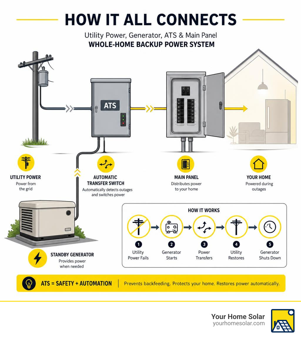
200 amp transfer switch installation is the key step that connects your standby generator to your entire home — automatically, safely, and without backfeeding power onto the utility grid.
Here’s a quick overview of how it works:
- Utility power fails — the ATS detects the outage within seconds
- Generator starts — the ATS sends a start signal to your standby generator
- Power transfers — the ATS switches your home’s load from utility to generator (break-before-make)
- Utility restores — the ATS detects returning utility power and transfers back automatically
- Generator shuts down — after a cooldown cycle, the generator returns to standby mode
A 200 amp ATS is rated for full residential service — handling up to 22,000 RMS symmetrical amperes at 240 VAC — making it the right match for a standard 200 amp home service panel.
Getting the installation right matters. Loose terminations, missed permits, improper grounding, or a double neutral-ground bond can create serious safety hazards or fail inspection. This guide walks through every step so you know exactly what’s involved.
I’m Ernie Bussell, founder and CEO of Your Home Solar, and my background in quality assurance, electrical systems, and overseeing large-scale residential installations gives me a grounded perspective on what a proper 200 amp transfer switch installation actually requires. Let’s break it down step by step.
What a 200 Amp Automatic Transfer Switch Does
An automatic transfer switch (ATS) acts as the brain of your home’s emergency standby system. When a storm rolls through East Tennessee and knocks out the grid, the ATS is what stands between your home and total darkness.
Unlike manual transfer switches, which require you to stumble out to the garage or exterior wall in the dark to throw a heavy metal lever, an ATS operates completely hands-free. A service-rated ATS constantly monitors incoming utility voltage and frequency. When it detects a sustained drop or complete loss of utility power, it initiates an automated sequence:
- It closes a dry contact to send a generator start signal to your standby generator’s controller.
- It waits for the generator to reach stable operating voltage and frequency (usually 60 Hz).
- It performs an open transition (also known as “break-before-make”) switch. This mechanical interlock ensures that the utility line and the generator line can never be connected to your home’s electrical panel at the same time. This absolute isolation is essential for backfeed prevention, protecting utility lineworkers who are working hard to restore power in your neighborhood.
- It safely routes the 120/240V split-phase power from the generator to your home’s electrical loads.
Under National Electrical Code (NEC) Article 702, standby systems like these are classified as optional standby systems. This means they are not legally required for life safety but are installed to protect property, maintain comfort, and keep home offices running. To comply with safety standards, any transfer equipment used in these systems must carry a UL 1008 listing, ensuring the switch can handle high fault currents without catastrophic failure. For a deeper look at the technical specifications of these units, you can review the Manufacturer 100–200A ATS installation manual.
How the ATS Integrates With the Main Service Panel and Generator
To understand where the ATS fits, let’s look at the path electricity takes. Normally, utility power flows from your electric meter, through the main service disconnect (the main 200A breaker), and into your main panel to feed your branch circuits.
When we perform a 200 amp transfer switch installation, we intercept this path.
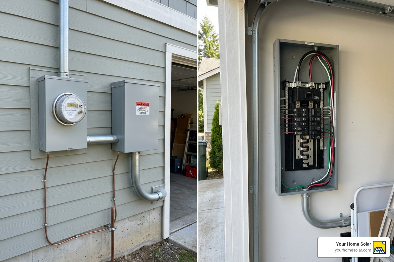
In a service-entrance-rated ATS setup, the transfer switch is installed on the load side of the meter but on the line side of your home’s distribution circuits. Because the ATS has its own built-in service disconnect breaker, it becomes the first point of control for your electrical system.
Consequently, your old main panel downstream is converted into a subpanel. This conversion requires us to run a 4-wire feeder (consisting of two hot lines, a neutral, and a separate equipment grounding conductor) from the ATS to the main panel, ensuring that the neutral path and the ground path remain completely isolated downstream of the ATS.
Additionally, low-voltage control wiring is run between the generator controller and the ATS. These control wires carry the 12V or 24V DC signals that monitor the system and command the generator to start.
Advanced ATS models also feature integrated digital power management, such as a Smart A/C Module (SACM). This module monitors generator frequency and automatically sheds heavy HVAC loads if the generator experiences an overload condition, restoring them sequentially once the system stabilizes.
Service-Rated vs Non-Service-Rated Transfer Switches
Choosing between a service-rated and a non-service-rated transfer switch is one of the most important decisions in the planning phase.
- Service-Entrance-Rated ATS: This unit contains a built-in main overcurrent protective device (circuit breaker). Because it serves as the first disconnect after the utility meter, the main bonding jumper is installed inside the ATS, establishing the single neutral-to-ground bond at this point. All downstream panels must have their neutrals and grounds separated.
- Non-Service-Rated ATS: This unit does not have a main circuit breaker. It must be installed downstream of an existing main service disconnect (such as an exterior meter-breaker combo or an existing main breaker panel). In this configuration, the neutral-to-ground bond remains at the upstream disconnect, and the ATS is wired using a 4-wire system with isolated neutrals and grounds.
It is critical to note that you should never modify factory wiring inside listed meter-main assemblies or panels to force-fit a non-service-rated ATS. Doing so violates the equipment’s UL listing and will cause a code violation during inspection. If you want to learn more about selecting the right model for your home, check out the Generac 200A Transfer Switch | Full Buyer Guide – IB Lighting and the 200 Amp Transfer Switch for Whole-Home Generator Systems – IB Lighting.
Pre-Installation Planning for a Safe, Code-Compliant Setup
Before picking up a single tool, proper planning is essential. A successful 200 amp transfer switch installation requires coordinating with your local building department (the Authority Having Jurisdiction, or AHJ) and your local utility provider (such as Knoxville Utilities Board or local electric co-ops).
You must secure the necessary electrical permits before starting any work. To make sure you are prepared for any unexpected grid failures, it is highly recommended to read Don’t Get Caught Off Guard: The Ultimate Guide to Emergency Home Power.
Planning also involves executing a thorough load calculation to ensure your generator is sized correctly to handle the loads routed through your 200A ATS. You must plan your physical layout, including:
- Conductor routing from the meter to the ATS, and from the ATS to the generator and main panel.
- Trenching pathways for underground conduits.
- Sizing of conduits and selecting wet-location fittings for outdoor runs.
- Verifying the Short-Circuit Current Rating (SCCR) field marking on the exterior of the ATS enclosure to ensure it matches or exceeds the available utility fault current (typically rated for 22,000 RMS symmetrical amperes at 240 VAC).
- Ensuring compliance with NEC 110.26, which mandates a minimum working space of 36 inches in depth, 30 inches in width, and 6.5 feet in height in front of the ATS for safe access and maintenance.
Tools and Materials Required
Having the right tools and materials on hand prevents delays and ensures a safe, code-compliant installation:
- Safety & PPE: Safety glasses, insulated gloves, and arc flash protection.
- Testing Instruments: CAT III rated digital multimeter (such as a meter meeting UL 3111 standards) and a lockout/tagout (LOTO) kit.
- Hand Tools: Insulated screwdriver set, wire strippers, heavy-duty wire cutters, conduit bender, and a calibrated torque wrench.
- Conductors: 3/0 AWG copper or 4/0 AWG aluminum conductors for the 200A main power lines, plus minimum 16 AWG conductors for control and sensing circuits.
- Installation Hardware: NEMA 3R rated transfer switch enclosure, listed lugs (supporting #6 to 250 MCM wire range), an auxiliary grounding bus, liquid-tight conduit and fittings, expansion joints for outdoor conduit runs, and anti-oxidant joint compound (for aluminum terminations).
Technical Specifications and Wiring Requirements
A 200 amp ATS requires precise electrical connections to operate safely. The table below outlines the typical wiring specifications for a standard single-phase residential installation:
| Conductor Function | Typical Wire Size (Copper) | Typical Wire Size (Aluminum) | Terminal Lug Torque Specification |
|---|---|---|---|
| Utility Line (L1/L2) | 3/0 AWG | 4/0 AWG | 275 in-lbs (31 Nm) |
| Generator Emergency (E1/E2) | 3/0 AWG | 4/0 AWG | 275 in-lbs (31 Nm) |
| Load Feeders (T1/T2) | 3/0 AWG | 4/0 AWG | 275 in-lbs (31 Nm) |
| System Neutral | 3/0 AWG | 4/0 AWG | 275 in-lbs (31 Nm) |
| Equipment Ground | #6 AWG | #4 AWG | Per manufacturer specification (typically 120–150 in-lbs) |
| Control & Sensing | #14 to #18 AWG | N/A | Per manufacturer specification (typically 15–20 in-lbs) |
Note: Always verify conductor ampacity and torque specifications on the specific equipment decal or owner’s manual before finalizing connections.
Choosing the Best ATS Location and Mounting Method
For residential installations in East Tennessee, we almost always recommend mounting the ATS in a NEMA 3R weather-proof enclosure. This allows for both indoor and outdoor mounting.

When selecting a location, follow these best practices:
- Structural Support: Mount the enclosure vertically to a flat, rigid supporting structure (such as a wood-framed wall or concrete block) and ensure it is perfectly plumb.
- Proximity: Keep the ATS as close as possible to the main electric meter and the existing service panel to minimize long, expensive runs of heavy 3/0 or 4/0 wire.
- Environmental Clearances: Position outdoor units well above historical flood levels, clear of winter snow accumulation zones, and away from dense vegetation or downspouts.
- Physical Safety: Ensure the door can swing open at least 90 degrees and can be locked to prevent unauthorized access.
Step-by-Step 200 Amp Transfer Switch Installation
Now, let’s dive into the physical installation process. A 200 amp transfer switch installation involves working around high-voltage utility lines that cannot be turned off by a simple household breaker.
Safety Warning: This process should only be executed by a trained, licensed electrician. DIY shortcuts can lead to severe injury, electrocution, or house fires.
For specific model configurations, you can refer to the Integrated 200A meter transfer switch manual.
Step 1: De-Energize, Verify, and Lock Out the System
Before touching any wires, we must completely de-energize the workspace:
- Coordinate with your local utility provider to pull the electric meter or disconnect utility power at the pole.
- Turn off the main breaker in the home’s service panel.
- Apply a lockout/tagout device to the utility disconnect to prevent accidental re-energization.
- Put on your personal protective equipment (PPE).
- Open the main panel cover and use a CAT III rated digital multimeter to test for voltage. Verify “test-before-touch” by checking hot-to-hot, hot-to-neutral, and hot-to-ground. Ensure all readings show 0 volts before proceeding.
Step 2: Mount the Transfer Switch Enclosure
With the power safely cut, you can mount the physical box:
- Mark the mounting hole locations on the wall surface, ensuring the unit is level and at an easily accessible height.
- Drill pilot holes and secure the enclosure using heavy-duty wood screws (for wall framing) or masonry anchors (for brick or concrete).
- Punch out the necessary conduit knockouts on the bottom or lower sides of the enclosure. Avoid punching holes in the top of an outdoor enclosure to prevent rain intrusion.
- Run your conduits between the ATS, the meter socket, the generator, and the main panel. Install wet-location fittings and bonding bushings where required.
Step 3: Connect Utility Conductors to the ATS Line Terminals
Next, wire the incoming utility power:
- Pull your utility service entrance conductors (L1, L2, and Neutral) through the conduit into the top section of the ATS.
- Group all current-carrying conductors together in the same conduit run to prevent stray magnetic fields and destructive enclosure heating.
- Strip the ends of the wires to the manufacturer’s recommended length.
- Apply a thin layer of anti-oxidant joint compound to the stripped ends if using aluminum conductors.
- Insert the hot conductors into the line terminals (commonly labeled N1 and N2) and the neutral into the neutral block.
- Use a calibrated torque wrench to tighten the lugs to exactly 275 in-lbs (31 Nm). Do not guess — under-torqued connections will overheat under load.
Step 4: Connect Generator Conductors to the ATS Emergency Terminals
Now, connect the backup power source:
- Pull the generator feeder conductors (L1, L2, Neutral, and Ground) from the generator’s main circuit breaker into the ATS.
- Connect the hot lines to the emergency terminals (commonly labeled E1 and E2).
- Connect the generator neutral to the neutral block.
- Connect the equipment grounding conductor to the ground bus.
- Pull the low-voltage control and sensing wires through a separate conduit (do not run low-voltage and high-voltage wires in the same conduit unless the control wires are rated for the higher voltage). Connect these to the signal terminal block according to the generator manufacturer’s schematic.
- Torque all power terminals to 275 in-lbs (31 Nm).
Step 5: Connect ATS Load Terminals to the Main Panel
Finally, connect the ATS to your home’s distribution panel:
- Pull the load conductors from the ATS load terminals (commonly labeled T1 and T2) into your main panel.
- Connect the neutral conductor to the main panel’s neutral bar.
- Connect the equipment grounding conductor to the main panel’s ground bar.
- In the main panel, you must isolate the neutral bar from the metal enclosure by removing the green main bonding screw or bonding jumper.
- Ensure the ground bar remains securely bonded to the panel enclosure. This maintains the clean, separate paths for neutral and ground required for all subpanels.
- Torque all load-side terminals in the ATS to 275 in-lbs (31 Nm).
200 Amp Transfer Switch Installation Neutral and Ground Rules
The absolute golden rule of any 200 amp transfer switch installation is maintaining a single neutral-to-ground bonding point for the entire system.
If your ATS is service-entrance rated, this is your first disconnect. Therefore, the main bonding jumper must be installed inside the ATS. The neutral block in the ATS will be connected to the ground bus via a factory-installed copper strap or wire.
In the downstream main panel (which is now a subpanel), the neutral and ground bars must be completely separated. If you fail to separate them, neutral current will split and return to the utility on both the neutral and ground wires, creating a dangerous continuous ground-loop current on metal water pipes and appliance chassis.
Before energizing the system, always use an ohm meter to verify that there is infinite resistance (no continuity) between the neutral bar and the ground bar in your downstream panel.
Safety, Testing, Commissioning, and Long-Term Maintenance
Before restoring utility power, we must perform a series of structured functional tests. If you are planning a complete standby setup in the Knoxville area, be sure to check our dedicated Generator Installation Knoxville service page for professional assistance.
200 Amp Transfer Switch Installation Safety Best Practices
To ensure a lifetime of safe operation, always adhere to these professional standards:
- No Double-Lugging: Never insert more than one conductor into a terminal lug unless the lug is specifically listed and marked for multiple wires.
- Avoid Undersized Conductors: Never use wire sizes smaller than 3/0 copper or 4/0 aluminum for a 200A continuous load.
- Keep Enclosures Locked: Always keep the ATS door closed and locked to prevent children, pests, or moisture from entering.
- Apply Warning Labels: Place clear, weather-resistant labels on the meter base and main service panel indicating that a standby generator is installed on the property.
How to Test and Commission the ATS After Wiring
With all connections verified and torqued, you are ready to commission the system:
- Manual Operation Test: With all power sources off, use the manual transfer handle inside the ATS to switch the mechanism back and forth between “Utility” and “Standby” to ensure smooth mechanical movement. Return it to the “Utility” position.
- Voltage and Phase Verification: Have the utility company restore power. With the generator off, measure the voltage at the utility line terminals (N1/N2). You should read approximately 240V hot-to-hot and 120V hot-to-neutral.
- Generator No-Load Test: Start the generator manually using its controller. Measure the voltage at the emergency terminals (E1/E2) to verify it matches the utility voltage and frequency (60 Hz).
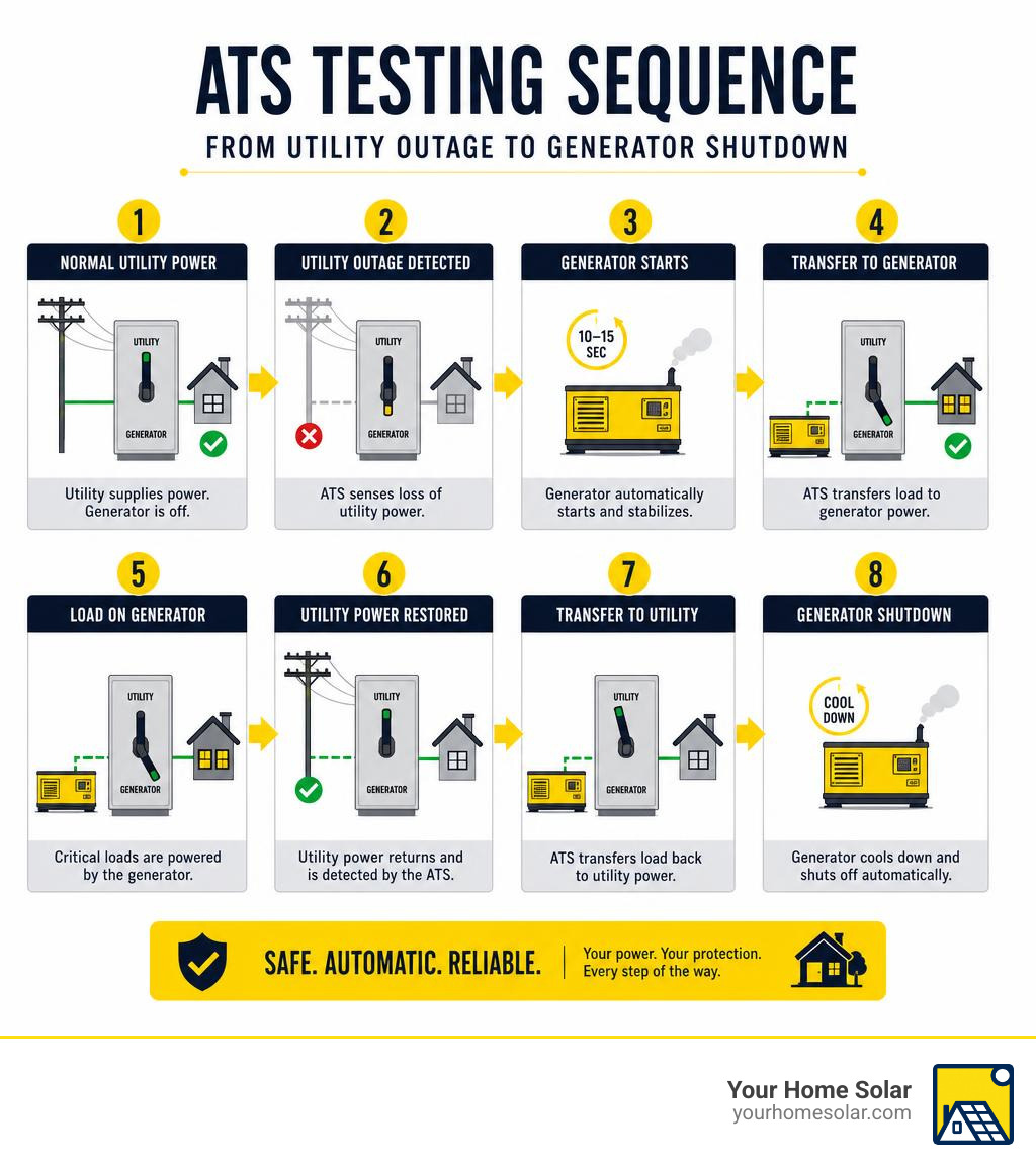
- Outage Simulation: Switch the generator controller to “Auto” and turn off the utility main disconnect breaker in the ATS.
- The generator should start automatically within 10 to 15 seconds.
- The ATS mechanism should click over to the standby position, restoring power to your home.
- Verify that critical loads and HVAC systems start up normally.
- Retransfer Test: Turn the utility main disconnect breaker back on.
- The ATS will monitor utility power for a preset time (typically 15 to 30 seconds) to ensure it is stable.
- The ATS mechanism will snap back to the utility position.
- The generator will run for a cool-down period (usually 1 to 5 minutes) and then shut down automatically.
Common Mistakes and Code Violations to Avoid
Working on hundreds of homes across East Tennessee, we regularly see the same installation mistakes. Avoid these common pitfalls:
- Modifying Listed Meter-Mains: Trying to tap into or unbolt components inside a factory-sealed meter-main combo to insert an ATS. This voids the manufacturer’s warranty and UL listing.
- Skipping Permits and Inspections: Operating a standby system without local electrical inspector sign-off can invalidate your homeowner’s insurance policy in the event of an electrical fire.
- Improper Torque: Tightening lugs with standard hex keys rather than a calibrated torque wrench. Loose lugs expand and contract under load, eventually causing electrical arcing.
- Leaving the Generator Neutral Bonded: Most standby generators come from the factory with the neutral bonded to the generator frame. If you connect this to a service-entrance-rated ATS (where the neutral is already bonded to ground), you create an illegal double-bond. You must remove the bonding jumper at the generator.
Maintenance and Inspection Schedule
An ATS is a highly reliable device, but it still requires regular care to ensure it performs perfectly when the next storm hits:
- Weekly: Ensure your generator runs its automated weekly exercise cycle (typically 5 to 12 minutes) to keep the engine lubricated and the ATS control circuits active.
- Monthly: Perform a quick visual inspection of the ATS enclosure. Check for debris, insect nests, or moisture ingress around the conduit seals.
- Annually: Hire a licensed professional to perform an annual service. This includes opening the enclosure, verifying terminal lug torque, testing the Smart A/C Module load-shedding relays, and inspecting the door gaskets. If you are evaluating your overall emergency backup options, you might also want to read about Don’t Be Powerless: Top Home Battery Backup Solutions.
Conclusion
A 200 amp transfer switch installation is the ultimate upgrade for any homeowner seeking true, whole-home power resilience. By automating the transition between grid power and your standby generator, you ensure your family remains safe, warm, and connected through any outage.
While this guide outlines the rigorous steps required for a safe installation, handling high-voltage utility service lines is a job best left to the experts. At Your Home Solar, we specialize in delivering tailored, reliable, and rewarding energy solutions across East Tennessee — from Knoxville and Maryville to Oak Ridge, Johnson City, and Sevierville.
Ready to protect your home with the ultimate backup power setup? Schedule generator installation support in Knoxville with our trusted team today, and let us handle your installation with 100% customer satisfaction guaranteed!